SHD2 - Dual Signal Head Decoder
Discontinued
Available from RR-CirKits.
The SHD2 is a DCC compatible signal head accessory decoder. The SHD2 does not contain any signal logic. It decodes DCC signal packets to drive two signal heads. It can drive four individual LEDs (4 colors) per head. A total of eight outputs. It is compatible with JMRI Signal Heads and Team Digital CSC(e).
MSRP - 13.95 USD
Manual in PDF format
4/9/14 - Version 2 is available which includes an option to control aspects with turnout (switch) commands. This option allows the SHD2 to work like the Digitrax SE8C and is compatible with RR&Co. software. If you want a SHD2 with this option be sure and request version 2. Version 2 shows in the SHD2 package.
Version 2.1 includes an option for aspect memory.
Manual V2 in PDF format
Features:
• DCC compatible signal accessory decoder
• Control 2 signal heads (4 aspects each)
• Easy signal mast wire connections
• Built-in resistors for LED drive
• Prototypical lamp fade
• Brightness adjustment
• Independent control of lunar aspects
• JMRI signal head compatible
• Digitrax signal mast compatible
• Connector pins and heat shrink tubing included
Operation:
The SHD2 works out of the package with no programming (address 1 for head 1 and address 2 for head 2). Additional SHD2s will require address changes. The SHD2 responds to DCC signal decoder packets as defined by the JMRI 'DCC Signal Decoder'. The SHD2 turns on an LED based on an address and aspect number.
The SHD2 is not compatible with incandescent lamps, LEDs with integrated resistors or 2-lead bi-color LEDs.
Application:
One possible way to mount the SHD2 is with an adhesive backed wire clip such as the Gardner Bender (GB) GWC-1510. Before inserting the SHD2 in the wire clip, release some of its tension by opening the clip several times. The SHD2 should slip into the clip relatively easy to avoid any physical damage.
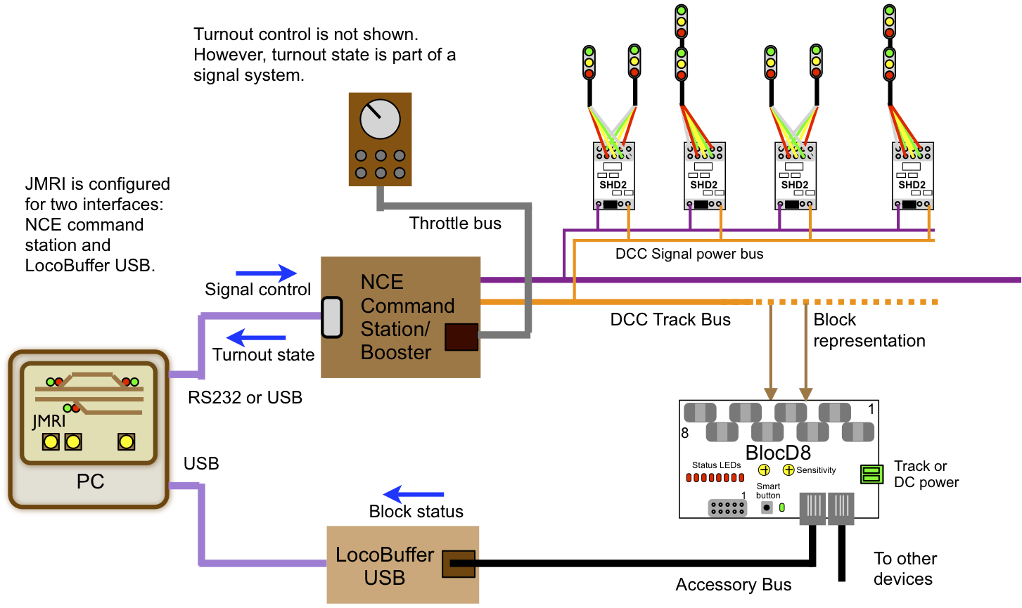
The following diagram shows how several SHD2s can work as a signal system in a NCE system. This also applies to any DCC system that can interface to JMRI. Based on turnout state and block status, JMRI provides the logic that determines which signal head aspect (color) should be on.
Note: The accessory bus and NCE throttle bus use the same 6 pin connector. However, they are not compatible. DO NOT connect them together.