SMC4 - Servo & Motor Controller
Animate your layout with semaphores, crossing gates and roundhouse doors. Move turnouts at prototypical speed. All controlled via DCC with the SMC4.
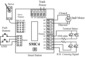
The SMC4 is a DCC compatible accessory decoder capable of driving four servo motors and four Tortoise™ switch machines. Each output can individually be assigned any address from 1 to 2040. It has eight inputs for local control of the outputs and 16 programmable routes.
MSRP - 49.95 USD
Manual in PDF format
SMC4 Tech Talk Videos - for a couple of applications including - Semaphores and Roundhouse doors.
Features:
• DCC compatible accessory decoder
• Controls 4 servos and 4 Tortoise™ motors
• "Power Save" greatly reduces current requirements
• Programmable position, range and speed of servos
• “Speed_to_Position”
• Inputs for local control of servos and motors
• Remote controlled routes for turnouts
• Dash Pot (buffer cylinder) Speed Feature - version 15 or higher
Operation:
There are several modes of operation. The modes are grouped into two basic configurations based on how the servo is used.
The first basic configuration is moving servos to two positions.
Mode 1 - The servo outputs and stall motor outputs can be used for turnout control. There is a separate address for each output so they can be controlled individually. There are a total of eight switch addresses. In this mode a servo could also be used for crossing gates. An option allows for stall motor output 5 to flash LEDs in relation to servo 1.
Mode 2 - The servo outputs and stall motor outputs can be used for turnout control. The servo outputs and stall motor outputs have the same address. There are a total of four switch addresses. The stall motor outputs can be used to drive LEDs to show the state of the servo outputs or drive a relay for turnout frog power routing.
The second basic configuration is for moving servos to three positions.
Mode 3 - The servo outputs can be used for semaphore control and the stall motor outputs can be used for turnout control. There are a total of 16 switch addresses. 12 addresses for the servo outputs and four addresses for stall motor outputs.
In this mode three addresses are used to control each servo, address A(throw) will command the servo to one end, address A+1(throw) will command it to the center and address A+2(throw) will command it to the other end. An optional behavior for each servo is available to use only a single address A(throw) to sequence or rotate through all three positions. Each time that address command is issued the servo moves to the next position (red > yellow > green > red ..etc).
Mode 4 - The servo outputs are used for semaphore control and the stall motor outputs can be used for turnout control. Four switch addresses control the stall motor outputs. The servo outputs are ONLY controlled by inputs (two inputs per servo output). This provides for direct control of 4 semaphores by block detectors for 2 blocks of bi-directional travel or 4 block for single direction travel. More block detectors and SMC4s can be ganged together in this way to easily expand the system.
Servos can easily draw 2 or 3 times the current of a Tortoise™. "Power Save" is a default option that essentially allows the SMC4 to remove operating power from the servo when it is not moving. Since turnouts are not operated continually this can 'save' a lot of power.
“Speed_to_Position” is an optional behavior that allows the throttle to variably control the position of the servo. Just as the throttle can be used to change an engine’s speed, so can it be used to control the position of a servo. The throttle speed step must be set to 128.
Two types of route control are supported. The remote controlled routes are controlled from the throttle just like a single switch is, except that multiple switches may be activated. The local routes are activated by using the inputs. Routes are configured by programming the respective CVs as to which outputs are selected in the route and the output state. Remote controlled routes are in two groups of eight. Each group has a group address to allow the throttle to access it.