DBD22 - DCC Block Detector Application Information
Block Detector:
The DBD22 can be used as a block occupancy detector for several of Team Digital products, but specially for the SIC24 (SIC24 refers to SIC24AD also). The DBD22 can operate from 5 volts which the SIC24 provides on its input connectors. The DBD22 output voltage levels are then compatible with the SIC24 inputs. See SIC24 application information for a diagram of two DBD22s connected to a SIC24.
The DBD22 is designed to sense high frequency DCC AC current and will not work with DC current or 60 cycle AC current.
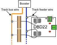
The following diagram shows an example of how the DBD22 can be wired to the track main bus. The feeder wires that pass through the DCD22 detection sensors should be no larger than 18 ga. stranded wire or 22 ga. solid wire. Care should be used when passing the wire through the sensors as they are fragile.
Sensitivity Issues:
There are several reasons why the DBD22 may indicate a block is occupied when in fact there is no engine or rolling stock in the block.
A LED or some kind of indicator that is powered from the track.
A frog power controller.
A reverse loop controller.
High humidity conditions can cause a problem. Perhaps the ballast is damp for some reason. Water can act like a resistor between the rails. There can be enough distributed capacitance in the DCC wires to cause a small amount of current to flow and thus causing a false indication. To keep the capacitance to a minimum, place the DBD22 close to the block it is detecting. Keep the block feed wire or any of the block track feeder wires from running right next to other wires for long distances. Do not twist the block feed wire with another wire.
In some cases it may be desirable to decrease the sensitivity of the DBD22. A resistor connected between the holes near each of the current sensors will decrease the sensitivity. Start with a 10K resistor. The smaller the resistor value, the less sensitive. The resistor can be mounted on either side of the circuit board. Keep the resistor leads short.
You can use the DBD22 for over current warning by connecting a buzzer to one of its outputs. Experimentation will give you the exact trigger point desired.
The DBD22 is rated to trigger at a track current of 3 ma. If it is not detecting rolling stock the wheel set resistor may need to be changed. To get 3 ma of track current a wheel set of ~ 4.7K ohms is required with a track voltage of 14 volts or ~ 3.9K ohms with a track voltage of 12 volts. Since N scale track voltage is near 12 volts a lower (than HO) value of resistor will be required. The sensitivity of the DBD22 is rated at 70 deg F. As the temperature decreases so does the sensitivity.
The sensitivity of the DBD22 can be increased by passing the feeder wire through the sensor more than one time. However with additional passes through the sensor the maximum continuous current the sensor can handle is reduced. For example with two passes the maximum current is reduced from 5 amps to 2.5 amps. This can be done with a 5 amp booster if a fast acting solid state circuit breaker set for 3 amps is used.
Remote LED Indication:
The DBD22 can be used to drive a remote LED to show block occupancy status. The first diagram shows the DBD22 driving a remote LED. When the block becomes occupied the DBD22 turns on the LED.
The next diagram shows the DBD22 controlling a two lead bi-color LED. When the block is unoccupied the LED is green. When the block is occupied the LED is red. Notice that to drive a bi-color LED the auxiliary outputs are required. The normal outputs are an open collector type. This type output allows several DBD22 outputs to be ORed together. The auxiliary outputs are push pull type.
In each diagram only output 1 of the DBD22 is shown connected. Output 2 could be connected in any of the ways as output 1.
When driving a LED a resistor is required to limit the current in the LED.
Relay drive:
The DBD22 can drive a relay with a low current coil. The relay shown has a coil current of 30 ma and a contact rating of 10 amps (Digikey PB380-ND). A clamping diode is required when driving a relay to suppress the voltage spike.