SHD2 Simulation using CSC and JMRI
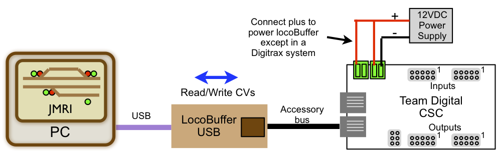
The purpose of the simulation is to provide a means to help develop and verify the CSC (Central Signal Controller) signal logic before any hardware is committed to the actual layout. It can also be used any time during the signal system installation. The only hardware required for the simulation is a computer with JMRI, a computer to loconet interface like a locobuffer and a CSC (+power supply and cables). See below.
JMRI simulates the layout including the signal heads, block occupancy and turnouts. It does not provide any signal logic.
Simulation example with two sidings
In this example with two sidings, four turnout and six blocks, a CSC is controlling 16 signal heads via eight SHD2s. A SHD2 drives two heads.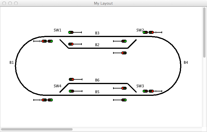
The sensor table can be used to control block occupancy by clicking on a State button. 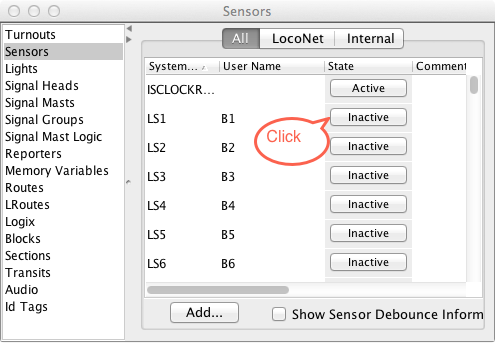
Layout showing one block occupied with the corresponding signal changes. The CSC received the block change information and changed the signals accordingly.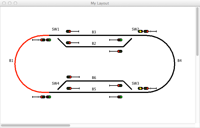
The sensor table showing how the State button changes.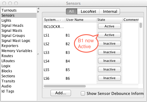
Turnout control can be done by clicking on the turnout. The CSC received the turnout change information and changed the signals accordingly.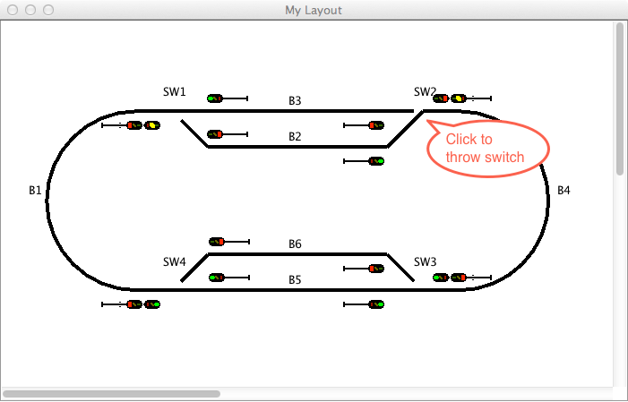
JMRI layout files are available here to download and experiment with. These files can be used with the respective CSC setup as described in the CSC manual.
Loop with two sidings csc_loop_scheme.xml - Shown above in the example.
Four blocks csc_4stBlocks_scheme.xml
APB signals csc_apb_scheme.xml
Grade crossing csc_gradecrossing_scheme.xml
Once the files are downloaded put them in the location as shown in the JMRI Preferences>File Location>User File Location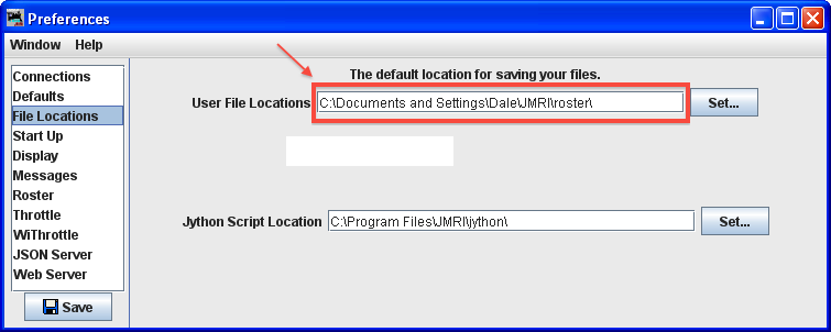
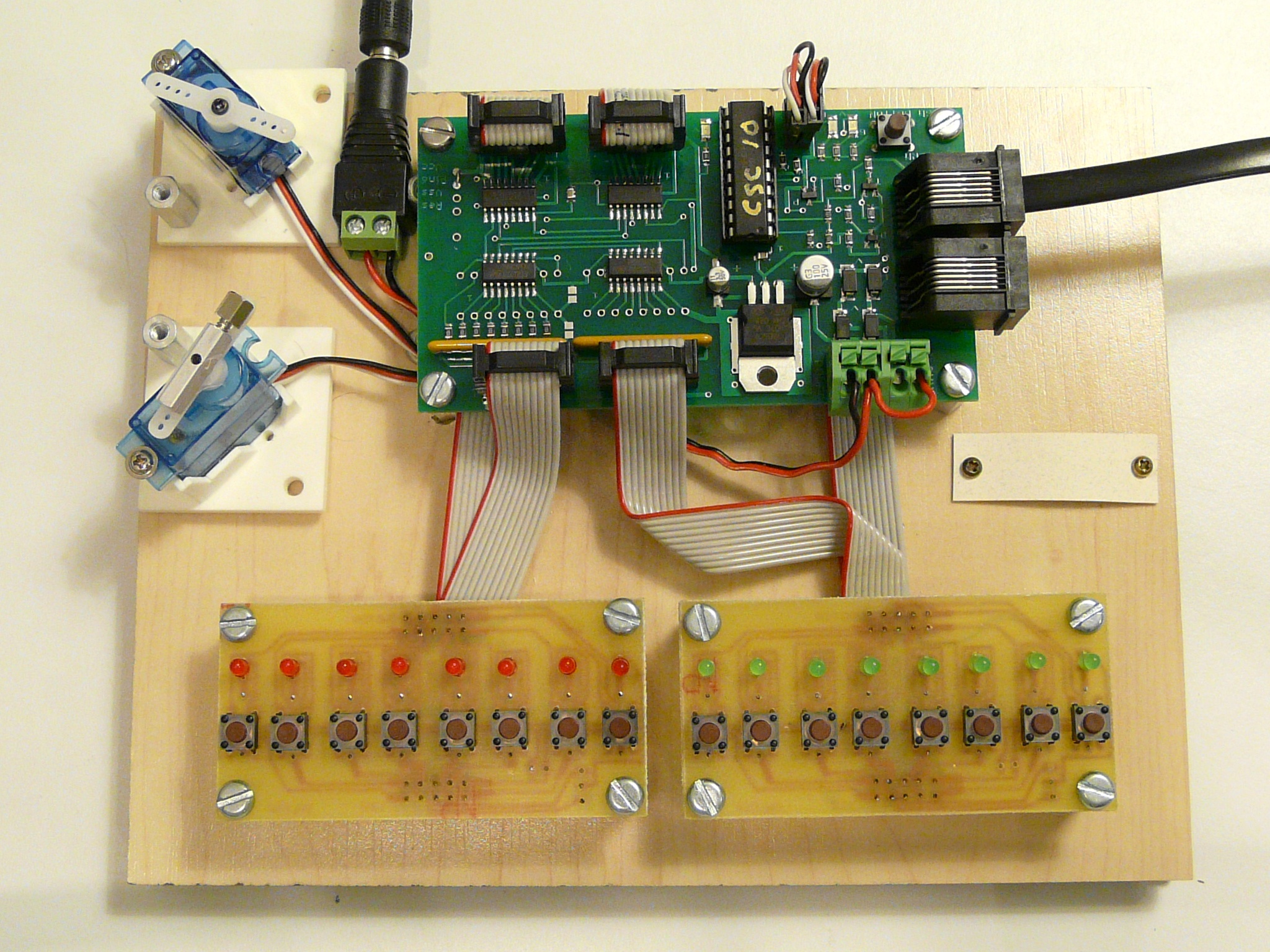
Overview of hardware to help develop Central Signal Controller signal logic.
Picture showing what can be used to help develop CSC logic. The LEDs are connected to the CSC outputs. The outputs can be programmed to show various logic cell states which helps in seeing what the logic is doing. The push buttons are connected to the CSC inputs and can be used to simulate block status, switch status or other items that may affect the signal logic.