SIC24 - Signal & Indicator Controller Application Information
General Information:
The SIC24 can be used in a number of applications. Various types of signaling systems, Centralized Traffic Control (CTC) panels and semaphore signal motor drive control are some types of uses for the SIC24. A computer is not required for controlling signals with the SIC24, but certainly could be used for enhanced operation.
To get the best performace from your SIC24, check out Tips for Successful Operation.
Known Problems:
4/29/05 - CV29 does not program correctly when the SIC24 is being programmed in page mode from the program track using a Digitrax system. Workaround - use direct mode programming.
SIC24s with this problem can be identified by a single silver mark on the integrated circuit (IC) closest to the bus connectors.
8/20/07 - Logic cells do not recognize secondary messages in version 17. If an input is programmed to send a primary and secondary message, the secondary message in not recognized by any logic cell in the SIC24 that sent the message. This means that any logic using a secondary message will not work. Also, since the SIC24 built in Setup 4 - Grade Crossing uses secondary messages it will not work correctly. Note that the secondary messages are sent correctly over the bus (loconet) and any other devices on the bus will not be effected.
SIC24s with this problem can be identified by 17 marked on the integrated circuit (IC) closest to the bus connectors. The SIC24 must be sent to Team Digital for software upgrade.
Specific Applications:
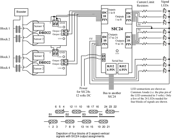
Below is a diagram showing a typical block signal system using a SIC24 and two DBD22s. This is the default signal configuration of the SIC24 as it comes from the factory.
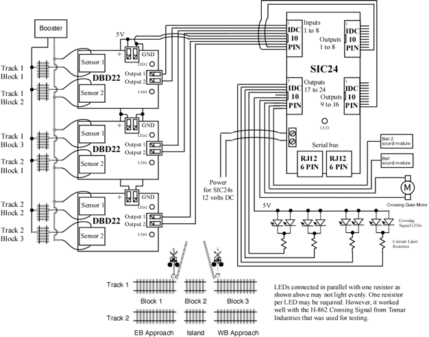
Below is a diagram showing a two track grade crossing with two bell sound modules using a SIC24 and three DBD22s. This is an example of the grade crossing setup. This setup is implemented in seven simple programming steps which include the option for one or two track operation and the option for a control of one or two bell sound modules.
The signal, bell and delayed gate lowering are initiated upon entering an approach. When the island is cleared the signal and bell stop and the gate is raised.
The minimum LED current limiting resistor value is 470 ohms. Resistor values of 1K work well with most LEDs. The higher the resistance value, the lower the power supply requirements.
10 Pin Connectors:
Both input and output connectors are the same. The Team Digital TSA board plugs directly into these connectors can be used for easy screw terminal connections. Also flat ribbon cable insulation displacement (IDC) type mating connectors can be used. Mating connectors and ribbon cable are available at some Team Digital Dealers and at.
Jameco : http://www.jameco.com
mating connector part # - 138377
10' flat ribbon cable, gray part # - 643794
10' flat ribbon cable, multicolor part # - 639672
connector installation tool part# - 73252