SIC24(AD)(e) - Logic Cell
Signal Logic
Signal logic is based on logical expressions, if a certain condition happens, then perform some action. If a switch (turnout) is closed then turn on a green LED. If a block is occupied then turn on a red LED. Logical operators can increase the power of the simple "If Then" statement. Some Logical operators are OR and AND. If a switch is thrown AND the siding is occupied then turn on a red LED. If the switch and siding occupancy do not both match these conditions then the red LED is not on.
The SIC24 family of signal controllers has logic cells that handle the signal logic. Note: SIC24e operates the same as the SIC24AD.
Logic Cell Introduction
The SIC24 family has several predefined Setups that automatically configure the logic cells (see the SIC24e user manual). However, in some cases if may be necessary to customize the SIC24AD logic cells. In order to customize it helps to understand how it works. Logic cells implement logical expressions as mentioned above.
Switch and block occupancy state are carried in "messages" (see below for more information on messages). When the SIC24AD receives a message, it is compared to all the logic cell elements to see if there is a match. If a received switch close message matches a particular logic cell element, then a match condition happens and the cell may change state depending on the logical operator. In the Logic Cell Simple Simulator below, Element A is set for switch 1 close. When a switch 1 close message is received, there is a match and logic cell 1 goes to True. Element B is not defined and has no effect on the logic cell with an OR operator.
Whenever a logic cell changes state a message is sent indicating its state. This message is treated by the SIC24AD just like it does other messages. The message contains the logic cell address which is determined by the SIC24AD base logic cell address.
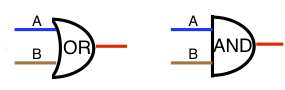
If may help to visualize a logic cell with logic symbols. Here is a OR and AND logic cell with logic elements A and B depicted.
Logic Cell Simple Simulator
The initial state of the simulator has Element A of logic cell 1 set for switch 1 close and logic cell 1 state is False. Click the Send button to send a switch 1 close message. Notice that the logic cell 1 state is now True. When this condition happened, the message matched the element and the logic cell's state changed. When a logic cell state is changed a sensor message is sent. Logic cell state messages are sensor type. Now select the message Type & State to Switch (t). Click the Send button. Notice logic cell 1 is now False. A LED is depicted as if it were connected to the SIC24 logic cell output pin. This simulates an action.
Messages carry various pieces of information including switch state, block occupancy state and logic cell state. Switch (turnout) state is called switch messages. It is used to command or request a switch to change states. Block occupancy state and logic cell state are called sensor messages. The messages carry not only the type, switch or sensor, but the related number or address i.e., switch number or logic cell address. A third type of message supported by the SIC24AD but not included in this simulator is switch feedback. The feedback message is typically used for switch state verification once the switch has been commanded to change states. Since switch, sensor and feedback are different types of messages, they can have the same address without a conflict. Messages are passed along the serial bus (Digitrax LocoNet® compatible) and are available to all the logic cells in the system i.e. all SIC24(s) connect via the serial bus. These messages are defined by Digitrax in their document (LocoNet® Personal Edition) located here. Note: a LocoNet® switch message is equivalent to a DCC switch command.
Whenever a logic cell changes state a sensor message with the logic cell address and state is sent on the serial bus. The logic cell address for each SIC24 is determined by the base address (default 101). A block of 24 addresses starting with the base address is used by each SIC24 since there are 24 logic cells per SIC24. If more than one SIC24 is connected via the serial bus then the base address should be changed so there are no duplicate logic cell addresses.
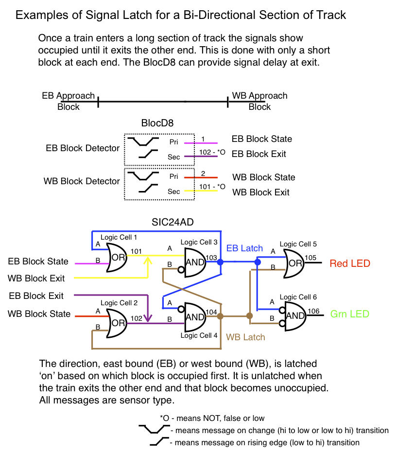
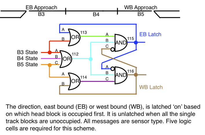
For those interested in using more of the SIC24s logic capabilities, here is an example of a latch. Also, It uses some of the features of the BlocD8. Being familiar with the respective user manuals is a prerequisite for a good understanding of this information.
More information about logic cells predefined Setups is available in spreadsheet form on the Support Tools page.
Download file sic24_cell_asign.xls