SIC24(AD)(e) Smart Programming
"Smart" programming is a term used to describe an easy way to program the SIC24AD and SIC24e. The throttle is used to issue switch or accessory commands just like controlling switches (turnouts). If you are not familiar with controlling turnouts or issuing switch commands, you will need to check your DCC systems manual.
For the purpose of this discussion, "throttle" refers to any device that can issue or send switch commands. "c" refers to Close or Normal switch position. "t" refers to Throw or Reverse switch position.
Smart programming is NOT done in service mode (program track) or operations mode (ops)/on the main but with a series of switch commands. The SIC24AD manual has detailed information on how to enter Smart programming mode. The SIC24AD must be powered from track power to use "Smart" programming.
Reset the SIC24AD to factory defaults.
To “reset” the SIC24AD to factory defaults, turn power on and wait until LED 1 (red) turns off (5 - 6 seconds). Then press the “Smart” button and continue to hold the button down (at least 16 seconds) until both LED 1 & 2 are alternately flashing. Release the button. The SIC24AD will now restart.
Switch state indication, Setup 3
In this example the SIC24AD outputs are configured to respond to switch commands. With LEDs connected to the outputs the SIC24AD can be used to indicate switch state. The inputs are not used.
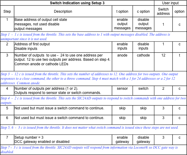
More on step 7. With the DCC gateway the serial bus is not required for the SIC24AD to display switch status.
In this example the SIC24AD outputs are configured to respond to switch commands. With LEDs connected to the outputs the SIC24AD can be used to indicate switch state. The inputs are not used.
More on step 7. With the DCC gateway the serial bus is not required for the SIC24AD to display switch status.
Signal head indication using JMRI, Setup 3
The SIC24AD can be used with JMRI as a simple input/output device. It can act as a LED driver for signal heads and as an input device for block status. In this example the SIC24AD outputs are configured to respond to switch commands since JMRI can use switch commands to control signals. The inputs are configured to send block information over the serial bus (Digitrax LocoNet® compatible) to JMRI. The inputs would have to be connected to a block detector like the Team Digital DBD22. Disable the inputs if block information will be available on the serial bus from block detectors like the Team Digital BlocD8. If you do not have a Loconet interface to JMRI see "More on step 7" below. Also disable the inputs since they can not be used. In JMRI use Signal Heads with triple output.
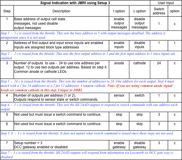
More on step 3. For a signal head, JMRI sends a switch command for each LED it controls. To turn on or light a LED it sends a throw command. To turn off a LED it sends a close command. The SIC24AD turns on a LED when it receive a close command. Just the opposite of the way JMRI works. So to compensate for this the SIC24AD outputs must be configured for the opposite polarity of the way the LEDs are wired.
More on step 7. The SIC24AD has a DCC gateway feature. This gateway will allow the SIC24AD to be a DCC accessory device even without using the serial bus. The gateway allows switch commands present on DCC (track) to be passed to the SIC24AD and handled just like ones on the serial bus. This means that the SIC24AD can be used in most DCC systems with JMRI.
The SIC24AD can be used with JMRI as a simple input/output device. It can act as a LED driver for signal heads and as an input device for block status. In this example the SIC24AD outputs are configured to respond to switch commands since JMRI can use switch commands to control signals. The inputs are configured to send block information over the serial bus (Digitrax LocoNet® compatible) to JMRI. The inputs would have to be connected to a block detector like the Team Digital DBD22. Disable the inputs if block information will be available on the serial bus from block detectors like the Team Digital BlocD8. If you do not have a Loconet interface to JMRI see "More on step 7" below. Also disable the inputs since they can not be used. In JMRI use Signal Heads with triple output.
More on step 3. For a signal head, JMRI sends a switch command for each LED it controls. To turn on or light a LED it sends a throw command. To turn off a LED it sends a close command. The SIC24AD turns on a LED when it receive a close command. Just the opposite of the way JMRI works. So to compensate for this the SIC24AD outputs must be configured for the opposite polarity of the way the LEDs are wired.
More on step 7. The SIC24AD has a DCC gateway feature. This gateway will allow the SIC24AD to be a DCC accessory device even without using the serial bus. The gateway allows switch commands present on DCC (track) to be passed to the SIC24AD and handled just like ones on the serial bus. This means that the SIC24AD can be used in most DCC systems with JMRI.