ABS Signaling with Semaphores controlled by the SMC4
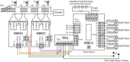
You can easily implement a 4 block control system with 2 DBD22s (block detectors) and a SMC4. By setting the SMC4 to Mode 4, you can use the inputs connected to DBD22s to move the servos to three positions. This provides an easy way to implement ABS signal control with semaphores. The primary input connector provides a 5 volt source, so DBD22s can be powered.
In mode 4, the SMC4 inputs are used exclusively to control four servos to three positions. Outputs 5 - 8 are still available to control Tortoise™ motors for turnout control.
Here are the connections of the DBD22s to a SMC4 for west bound travel. S1-S4 represent the semaphores and servos linked to the respective semaphore. Servos S1-S4 are connected to SMC4 outputs 1-4 respectively. B1- B4 indicate blocks. Also shown are Tortoise™ motors connected to the SMC4. In this drawing stall motor means Tortoise™.
The semaphore backlights are shown wired in series power from the TV (rectified track voltage) terminal. Lamps wired in series has a disadvantage in that if one burns out it is hard to determine which one. However if the current limit resistor value is chosen so that the lamps are running below their current rating, they will last a long time. Also, series wiring results in less current draw from the SMC4 and reduces the amount of wiring.
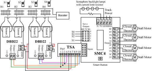
This is the same diagram as above with a Tortoise™ motor contact and a turnout (SW1) added. The outputs of the DBD22 are open collector which means that the outputs can be wired together (and with other devices) for OR type logic. Here the stall motor contact is wired to the same SMC4 input as a DBD22 output. In this case the contact closing will cause the same SMC4 response as B1 becoming occupied. So semaphore 1 will show red or stop if either block 1 becomes occupied or the turnout 1 is thrown.