SRC8 - Switch & Route Controller Application Information
General Information:
The SRC8 can be used in a number of applications. Track plan panels, Centralized Traffic Control (CTC) panels, fascia boards, motor drive and switch position reporting (feedback) are some types of uses for the SRC8.
The power supply connector is non polarized. Either terminal can be connected to plus or minus of the power supply. When multiple SRC8s are used they can be all connected to one power supply. The power supply must be able to supply the current for all the SRC8s. The plus and minus of the power supply must be connected to the same power input terminal on each SRC8.
Note: When two or more SRC8s are powered from the same power supply there can be a fault ground condition if one of the power wires to one of the SRC8s is loose. That SRC8 will still be getting power because loconet ground provides a power path to the SRC8 with the loose power wire. When this condition occurs, that SRC8 loads down loconet.
Be sure the power supply you use puts out the correct filtered DC voltage when connected to the SRC8. Most analog 'Power Packs' will not work because they do not provide smooth (filtered) DC power. Also it must be isolated from the system ground. That is, the power supply can not have one of it's outputs connected to ground (booster ground, loconet ground, house wiring ground, etc). Some wall transformers have a ground connection. Three prongs into the wall suggests the negative output of the power supply is grounded. Only SRC8s should be powered from this power supply.
The minimum LED current limiting resistor value is 470 ohms. This is a general guide line for a typical LED. Resistor values of 1K work well with many LEDs. The higher the resistance value, the lower the power supply requirements.
In the examples below only switch group 1 is shown being used. However, any group could be used and not all the groups have to be configured the same.
Known Problems:
10/21/02
Using alternate addresses. Activating an input sends the wrong alternate address. When an input in group 2 through 8 is activated, it actually sends it's alternate address plus it's group number minus one. The LEDs respond correctly to received messages with an alternate address. If you are not using alternate address, this problem does not effect SRC8 operation.
SRC8s with this problem can be identified by a single silver mark on the integrated circuit (IC) closest to the LocoNet connectors.
8/9/04
When CV 2, option 6 is enabled, group 1 inputs do not work. If you are not using option 6, this problem does not effect SRC8 operation.
SRC8s with this problem can be identified by four silver marks on the integrated circuit (IC) closest to the LocoNet connectors.
11/21/05
Using alternate addresses. If an alternate group address has been defined, the SRC8 will respond to a sensor type message in addition to the switch command message with the same address. To avoid this problem do not define an alternate address the same as a sensor address.
This problem has been corrected in version 4.3 of SRC8s (marked 43).
5/22/08
Executing routes. The second cell in a route does not operate correctly when inputs are configured for feedback reporting. SRC8s with this problem can be identified by 50 marked on the integrated circuit (IC) closest to the LocoNet connectors.
Arrange for problem solution by contacting us .
LED connections:
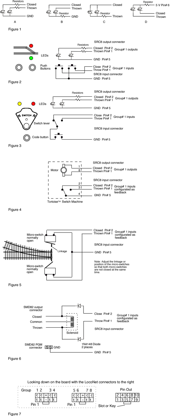
Figure 1 below shows three different configurations in which LEDs and the associated resistors could be connected to a SRC8 group output. In normal operation where only one of the group LEDs is turned on at a time, all three configuration work OK. However, during lamp check at power on and in "Smart Programming" mode when both LEDs are turned on, both LEDs in configuration Figure 1B may not be on and both LEDs in Figure 1C will be off.
Note that the LED configuration in Figure 1A can also represent a three legged bi-color LED (common cathode). While the configuration in 1C can represent two legged bi-color LEDs. Figure 1D can represent a three legged bi-color LED (common anode).
Track Plan Panel:
Figure 2 below shows how push buttons and LEDs can be connected to the SRC8 inputs and outputs. In this case, when a button is pressed, the LEDs show the state of the switch on a representation of the track plan. The push buttons could be located near the LEDs or some distance away on another panel.
The buttons could also be placed on a fascia board without the use of the LEDs to provide local control of a switch or a route.
CTC Panel:
Figure 3 below shows a CTC panel with a US&S configuration. The switch lever can be moved freely at any time. However, nothing happens until the button (sometimes called "code start button") is pressed. Once the button is pressed, the LEDs indicate the state of the switch.
Switch Machine Drive:
Figure 4 below shows how a low current stall type switch machine can be connected to the SRC8 outputs. The SRC8 has been tested with the Tortoise™ switch machine and can drive up to eight of them. Programming is the same whether using a switch machine or LEDs. The SRC8 is NOT compatible with the SwitchMaster motor.
Each switch machine is connected to one of the SRC8 group outputs. One of the motor terminals is connected to the closed (green LED) output and the other motor terminal is connected to the thrown (red LED) output. When the SRC8 receives a switch command for that group, lets say a close command, 5 volts is applied to the closed output. The thrown output is at ground, so 5 volts is applied to the motor. It then moves in the close direction. Likewise, when a throw command is received for that group, 5 volts is applied to the thrown output. The closed output is now at ground, so 5 volts is applied to the motor in the opposite direction. Consequently, it moves in the throw direction.
Since the SRC8 uses 5 volts for motor drive, the switch machine moves slower than if 12 volts were applied.
The inputs can be used to control the switch machine or can be configured as feedback as discussed next.
LEDs can be uesd as switch position indicators. The SRC8 does not have enough voltage output to drive a Tortoise™ in series with an LED. However, you can drive a Tortoise™ in parallel with a LED resistor combination (in this case the resistor should be at least 1000 ohms). You can also use the internal contacts of the Tortoise with a LED resistor combination powered by 5 volts from the SRC8 or by track voltage.
Switch Position Reporting:
The SRC8 can be used to report switch position which is sometimes called switch position feedback. In some situations it is desirable to know for sure that a switch actually moved when it was commanded. Figure 4 below shows the SRC8 inputs connected to the Tortoise™ switch machine internal contacts. Figure 5 below depicts micro switches mechanically linked to the switch and connected to the SRC8 inputs. When the switch moves internal contacts close or a micro switch is activated, grounding a SRC8 input. The SRC8 then sends a LocoNet feedback message.
10 Pin Connectors:
Figure 7 below shows the SRC8's connector pin out and group number relationship. The view is from the top of the connectors. Both input and output connectors have the same pin out. The Team Digital TSA board plugs directly into these connectors can be used for easy screw terminal connections. Also flat ribbon cable insulation displacement (IDC) type mating connectors can be used. Mating connectors and ribbon cable are available at some Team Digital Dealers and at.
Jameco : http://www.jameco.com
mating connector part # - 138377
10' flat ribbon cable, gray part # - 643794
10' flat ribbon cable, multicolor part # - 639672
connector installation tool part# - 73252