SHD2 - Dual Signal Head Decoder Application Information
General Configuration types:
There are two general configuration types of signal systems using the SHD2. The difference is where the signal logic is located. Signal logic is what decides which signal aspect should be red, green, etc.
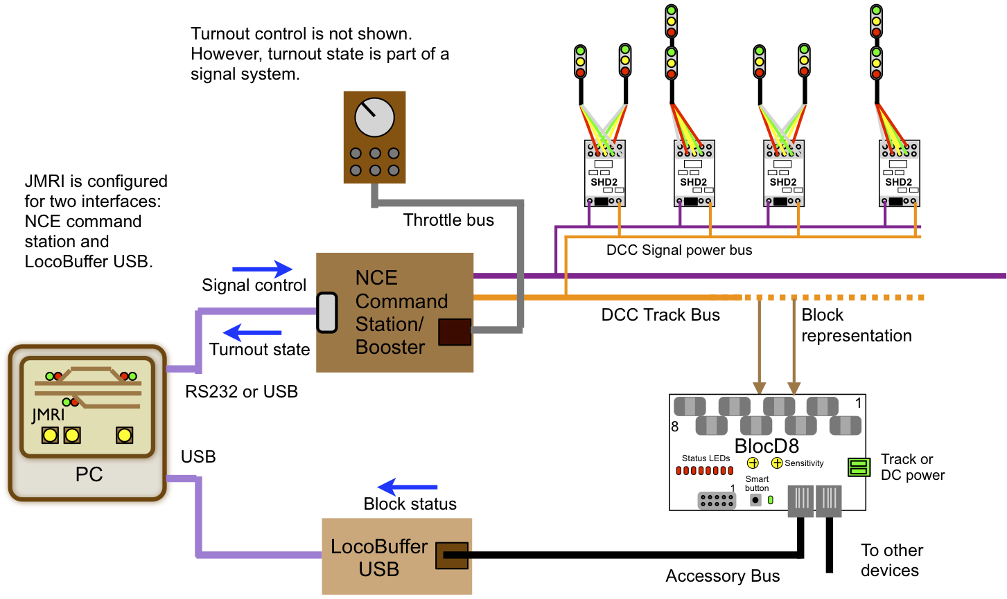
- JMRI DCC Signal Heads control - requires a computer ( see SHD2 and JMRI application )
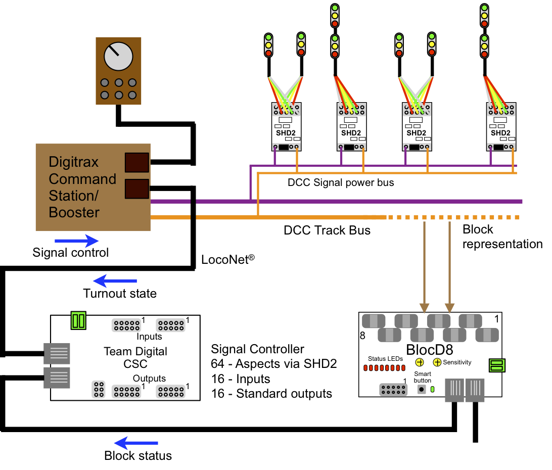
- CSC - Central Signal Controller - to help develop the CSC signal logic see SHD2 simulation
Signal Control from JMRI in a NCE system. Signal logic is in JMRI.
Signal Control from a CSC in a Digitrax system. Signal logic is in the CSC.
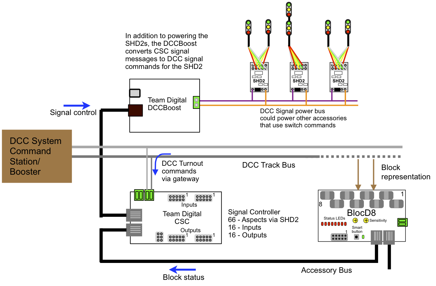
Signal Control from a CSC in a DCC system. Signal logic is in the CSC.
Power requirements:
When the SHD2 first powers on, it sequentially turns on each LED on each signal head at maximum brightness. During this time the SHD2 applies 5 volts through a 220 ohm resistor (100% duty cycle). After the sequence is complete the SHD2 applies 5 volts at a 50% duty cycle to the LEDs. This duty cycle can be changed for each LED to adjust the brightness. The higher the duty cycle the brighter the LED. See the SHD2 manual.
Not taking the LED voltage drop into account, the current required at power on per signal head would be (5/220)x2 = 45 mA. If there were 24 signal heads on the layout the current requirement would be .045x24 = 1.08 amps. If the duty cycle remained unchanged at 50%, the operating current would be about 0.5 amps after the SHD2 completed the startup sequence. However, the power supply must be sized for the power on requirement. In this example with 24 signal heads the current requirement is 1.08 amps.
Note: If the LED voltage drop were taken into account the current requirement would be lower. However, this type of calculation gives a good guide line for selecting the power supply.