DCC Decoder Addressing
Mobile or Locomotive Decoder - Control Locomotives
• Address (Cab#) - range 1 to 9999
• Name - speed, light on, sound on
• Street 1 - multi-resident dwelling
Stationary or Accessory Decoder - Control Turnouts
• Address - range 1 to 2040
• Name - close, throw
• Street 2 - multi-resident dwelling
Stationary or Accessory Decoder - Signal Heads
• Address - range 1 to 2040
• Name - aspect number
• Street 3 - multi-resident dwelling
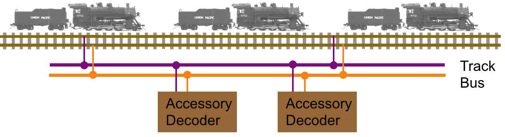
These decoders exist in the same city (connected to the same track bus) but on different streets. They are uniquely addressed even if the address number is the same.
Mobile or Locomotive Decoder
• 1 Circuit board per loco - 1 address
Stationary or Accessory Decoder - Control Turnouts
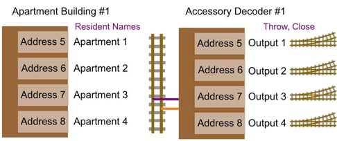
• 1 Circuit board - 1, 2....8 addresses (example SMD84) - A multi-resident apartment in an apartment building
A single accessory decoder can have multiple outputs each with an address. It can be compared to an apartment building.
Stationary or Accessory Decoder - Signal Heads
• 1 Circuit board - 2 addresses, 8 aspect numbers per head (example SHD2) - A multi-resident apartment in an apartment building
Digitrax Accessory Boards - Board ID number
Some Digitrax accessory products use board ID numbers. For example the SE8c signal board ID number sets a range of switch (turnout) addresses used for controlling signals. The ID number is not a loco, switch or signal address.
Using a Loco address in an Accessory Decoder
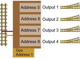
Locomotive decoders and some accessory decoders can be uniquely configured by the use of Configuration Variables called CVs. The DCC standards allow a locomotive decoder CVs to be programmed when it is operating on the main track. This is called Operations (Ops) mode programming or On the Main programming. Each loco decoder on the track can be programmed using it's unique address.
Current Team Digital accessory decoders have a feature that allows Ops mode programming. They have a Locomotive decoder type address. Using this address the accessory decoder can be programmed just like a Loco decoder. As mentioned above the Loco (Ops) address can be the same as one of the accessory outputs without a conflict. The Ops mode address can NOT be used to control any of the accessory decoders outputs. It is only used for programming.
In this example using Ops mode address of one (1), the four (4) output addresses were programmed from 5 to 8. These four outputs will respond to turnout commands of addresses 5 to 8. These outputs will NOT respond to a loco address of one (1) even if one of the output addresses were one (1).