Turnout and Signal control from a CTC Panel
General Operation:
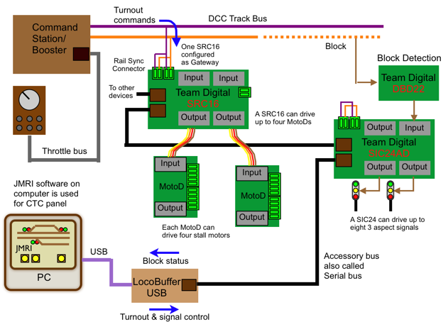
This scheme provides for turnout and signal control from a dispatcher using a Centralized Traffic Control (CTC) panel with Team Digital SRC162e(s), SIC24e(s) and DBD22(s) in a DCC system. Turnout control is also available via a throttle. It also demonstrates the concept of an accessory bus.
An accessory bus also called serial bus is defined as an independent serial bus separate from the throttle bus. It provides a way for accessory devices to communicate with each other. This can provide several advantages for a DCC system. An accessory bus can expand the selection of devices available for applications and can aid in trouble shooting.
The SRC162e is an accessory decoder and can be powered from DCC track power. Since it can be controlled via DCC commands it's gateway feature provides a very convenient way to pass turnout (switch) commands to the accessory bus. This allows DCC turnout commands to control devices connected to the accessory bus. Thus, turnouts can be controlled either from the throttle or from the dispatcher.
Turnouts:
SRC162e(s) are used to control turnouts and optionally indicate turnout status. They can drive stall motor type switch machine with 5 volts or with a higher voltage using MotoDs. With MotoDs the SRC162e control up to 16 stall motors.
Block Status:
DBD22(s) are connected to the SIC24e(s) to provide block status.
The SIC24e(s) send the block status information to the CTC panel for dispatcher use.
Signaling:
SIC24e(s) are used to drive the signal aspects. The specific aspect to light is determined by the dispatcher using the CTC panel. In this application the SIC24e is configured as a general input/output device. The SIC24e has 24 output to drive up to 24 LEDs or eight 3 aspect signals.
The accessory bus greatly simplifies wiring because the SIC24es can be located around the layout near the signal aspects they are driving. This means the DBD22s will be near the blocks they are detecting.
CTC Panel:
The CTC panel is depicted on a computer screen using software like JMRI. It allows the dispatcher to control turnouts and signals. The panel also shows block occupancy information.
The computer is connected to the accessory bus via a USB cable and a LocoBuffer USB. The accessory bus is compatible with Digitrax's LocoNet® so the computer software must be configured for a LocoNet® interface.
Power:
The SRC162e(s) and SIC24e(s) may be powered from a dedicated power supply or the track. Using the rail sync lines in a separate accessory bus provides easy power connections. DBD22(s) are powered from the SIC24e(s).
Note: SIC24 is sometimes used to refer to the original SIC24, the SIC24AD and SIC24e.. The original SIC24 can NOT be powered from the track.
DCC system with dispatcher control